
FM
Transmitter circuit kit FM exciters FM Transmitters FM Exciter
diy Broadcast RF Circuit electronic schematic ham free spy
Technical details of MAX-1's VCO
02nd - 06th May '99
My review of PCS Electronics' MAX-1 FM Exciter
kit
More technical details on the VCO
When I built my MAX-1, it did not lock across all its tuneable FM band of 86 to 110 MHz. Infact at low frequencies, the LCD would say "Compress L7" and at the high frequencies it would say "Expand L7", L7 being the frequency determining coil in the Oscillator LC Circuit.
Now that's not as bad as it first seems, especially in a higher power transmitter. To change frequency of operation, you would have to retune the antenna and retune the final power stage. Forcing you to also compress/expand a coil is not so much hard work, but it could have easily been avoided.
Basic principles :
A) The frequency of oscillation of an LC circuit can be
determined by the following formula :

f = frequency of Oscillation in Hz
Pi = 3.14159
L = Inductance of coil in Henrys
C = Capacitance of capacitor in Farads
B) A Varicap Diode (or Varactor) is a diode that changes its capacitance in relation to the reverse voltage applied. The more the reverse voltage, the lower the capacitance. Most diodes show some Varactor characteristics but a genuine Varactor has a larger range of capacitance.
From the formula above, we see that if a Varicap is part of the LC circuit, if we apply higher reverse voltage to the Varicap, it will have less capacitance so the LC circuit will oscillate at a higher frequency. Conversely lower voltage = lower frequency.
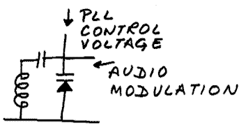
Replacing a Oscillator's LC capacitor with a Varicap is a simple way to make a Voltage Controlled Oscillator
See graph below of typical Voltage versus Capacitance values of the Philips BB204B Varicap.
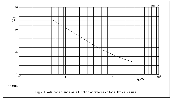
Typical values of Philips BB204B Varicap used in the MAX-1
| 0.5V : 62 pF 1.0V : 52 pF 2.0V : 45 pF 3.0V : 37 pF 5.0V : 30 pF |
6.0V : 28 pF 7.0V : 27 pF 8.0V : 25 pF 10 V : 22 pF 20 V : 17 pF |
Notice that the Voltage scale is logarithmic, so Varicaps are not linear in their Capacitance versus Voltage function.
In any case, as f depends on inverse square root of capacitance, f will never be linearly proportional to Voltage in the simple VCO circuits used by kits. Infact there is no requirement that the VCO's frequency be linear against applied voltage across a wide range of voltage. It needs only to be linear in the small range of Audio voltage applied, so that the frequency deviation is proportional to the Audio Modulation. This is easy as the Audio Voltage would only be about 0.02Volts and almost any VCO would be considered linear in such a small range. ( If VCO sensitivity is about 4 MHz/Volt then about 0.02 V of audio would give us the 75 KHz deviation we need)
C) The FM Band is from 88 to 108 MHz i.e. a range of 20 MHz. Suppose we use a 12 Volt supply to power the FM Exciter, we could easily have the PLL output maybe 4-9 Volts or even 2-10 volts i.e. about 5-8 Volts range.
To be able to tune across the whole FM band, we would then need the VCO to have a sensitivity of about 2.5 to 4 MHz/Volt.
From LC oscillation frequency formula above, if tunability range is 108 MHz / 88 MHz :: 1.227 : 1 then the capacitance range of the Varicap needed is atleast 1: 1.506 in between the PLL Voltage range of 2-10V.
The Max-1 PLL is programmable from 86 MHz to 110 MHz so the capacitance range needed is 1: 1.636
We can see that the BB204B has a capacitance of about 45 pF at 2V. To be useful for FM, it should be less than 45/1.506 = 30 pF at around 5 volts away i.e. 7 Volts. We see that actually it has 27 pF around 7 Volts so it is perfect for use in FM band oscillators to make a VCO with about 4 MHz/Volt sensitivity ( Can tune across 20 MHz with 5 Volt change in Voltage).
Higher sensitivity to control voltage also means higher sensitivity to noise in the control voltage. So designers normally design the VCO sensitivity not exceeding around 4 MHz/Volt.
D) In case we design the coil to be of too low an inductance value and then tried to set a low frequency of operation, we see from the LC oscillation frequency equation above that C should be high i.e. reverse voltage should be low. But you cannot have a reverse voltage below 0 and maybe you shouldn't design the PLL to lock below 2 V. Suppose we needed a capacitance of 75 pF to resonate the low L, we see that the PLL would never lock as the Varicap above can never have a capacitance of 75 pF. The PLL would make its control voltage as low as possible, maybe 2V, but that's not going to be good enough.
In this case, you have to increase the L, i.e. compress the coil.
E) On the other hand, in case we use a coil of too high an inductance value and tried to set a high frequency of operation, we see from the LC Oscillation frequency above that C should be low i.e. reverse voltage should be high. But normally the maximum PLL control voltage is 1 volt or so less than the supply voltage. Suppose we needed a capacitance of 10 pF to resonate the high L but we are supplying the kit with 12 Volts power, we see that the PLL would never lock as the Varicap will have more than 22 pF capacitance with less than 10 V reverse voltage. So the PLL would output its maximum voltage to try and lock but that would not be good enough.
In this case, you have to decrease the L, i.e. expand the coil.
F) So we see that in case Varicap has enough capacitance range across the PLL voltage range, correct value of Inductance will make the PLL lock across the whole range. Low value of L will lead to problems locking at low frequencies. High value of L will lead to problems locking at high frequencies.
But the MAX-1 did not lock at both ends of the Frequency Band !!
So looks like the BB204 Varicaps do not have sufficient capacitance range in the particular way they are used in the MAX-1, or the PLL control voltage is limited.
So lets investigate the MAX-1's set frequency versus PLL error
voltage.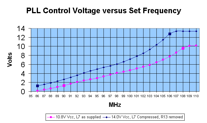
Pink Data points : L7 as supplied, Power
supply 10.8V DC
Blue Data Points : As the MAX-1 locked at
minimum 1.8V, I compressed L7 so that PLL Voltage was 1.8V at 86
MHz. I also increased the power supply voltage to 14.0 V DC to
try and get it to lock at higher voltages.
Bigger box : Start / End of PLL Lock range
From above graph, we see :
i) As expected, the VCO is not linear in the Voltage versus frequency function for wide range of Voltage.
If we consider only a small voltage change of 0.1V from any given voltage, we do see that the VCO is linear in that small range. So Frequency Modulation would be in direct proportion of Audio Modulation.
However we see that the VCO sensitivity is different at different points of its operating range. Around 90 MHz, sensitivity is about 3.00 MHz/V while around 106 MHz the sensitivity is about 1.17 MHz/V.
In case Audio was fed directly into a VCO with characteristics as above, the same level of Audio signal that modulates the Exciter properly at the low frequency end would only modulate about 1/3rd the desired frequency deviation at the high frequency end.
To reduce this problem, it is better to use one set of Varicaps for receiving the PLL Control voltage and another set of Varicaps to receive the Audio Modulation. As the Audio Modulation Varicaps would always be reverse biased at a fixed voltage, they would always operate at a fixed point of their Voltage versus Capacitance graph, so they would always modulate at the same level for the same Audio input, irrespective of the PLL control voltage. The MAX-1 does indeed use two different Varicaps.
ii) To lock below 89 MHz, the control voltage should be below 1.8V. As that is hard for the PLL to do, it has problems locking at the low end. The MAX-1's test function recommended compressing the coil when you set frequencies below 89 MHz. The Blue data points show response after compressing L7.
iii) At the high frequency end, we see that
with a power supply of 10.8V, the PLL is clipping around 10.3 V.
It cannot output a higher voltage than 10.3V. It appears that the
PLL can output up till Vcc - one diode voltage drop of 0.5V =
10.3V. So if you try and set a frequency of 107.5 MHz and above,
the PLL would go as high as possible but still not reach the
desired level of capacitance, so it would not lock. The MAX-1's
test function recommends expanding the coil when you set
frequencies above 107.5 MHz.
The Blue Data points show PLL voltage after Vcc was increased to
14.0 V DC.Here we see the PLL topping out at 13.3V
iv) We see that the average sensitivity of the VCO is about 2.27 MHz/Volt. This is a bit on the lower side as now you will need a PLL Voltage range of 10.57 Volts to cover the 24 MHz frequency range from 86 to 100 MHz. But the PLL seems to do only about 8 Volts range comfortably with 10.8V supply. Hence the problems at locking at both band extremes.
If the VCO sensitivity was higher at about 3 MHz/Volt, the MAX-1 would have been able to tune across the 24 MHz range with a PLL control voltage range of 8 Volts which the PLL can easily do.
So we have finally arrived at the reason and solution for the MAX-1's lack of lock at band extremes : VCO sensitivity.
Analysing the MAX-1's VCO circuitry :
Let's look at the MAX-1's VCO LC Circuit. Marko has used
two dual Varicaps. Each BB204 has two Varicaps built in.
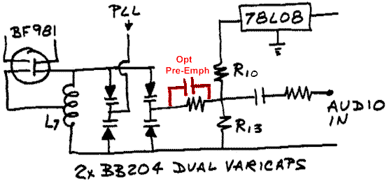
(Aside : Red bit shows where you could put in a Cap for Pre-emphasis. You would need this in case you are transmitting in Mono and there is no other Pre-emphasis in the Audio Chain i.e. if you connect your Walkman directly to the MAX-1)
If we analyse the LC circuit, we find that we can consider the two internal Varicaps of each BB204 as actually one Varicap of half the capacitance as the internal Varicaps are in series. Lets call the BB204 receiving the PLL voltage as Cp and the one receiving the Audio Modulation as Ca.
Ca can be considered as a fixed capacitor when there is no Audio in, because it is being fed a constant reverse voltage. This reverse voltage is generated from the 78L08 Voltage Regulator being Voltage divided by the R10/R13 network.

Temporary fix ? :
If the MAX-1 does not lock at the low end, you should compress L7
to increase its inductance. If that still does not work, we
should try and increase the total effective capacitance in the LC
Tank. If we feed the BB204B doing the Audio with less reverse
voltage, it will have more capacitance. Marko therefore suggests
changing R13 to lower values in the documentation.
Conversely in case the MAX-1 does not lock at the high end even after expanding L7, one should decrease the total capacitance in the LC tank. Marko therefore suggests removing R13 altogether.
This approach will definitely make the MAX-1 lock at the frequency you want but -
A) As the BB204 handing the Audio will now be working at different points in its Voltage/Capacitance graph based on the values of R13 chosen, the sensitivity to Audio will change.
B) It still does not guarantee that the MAX-1 will lock across the 24 MHz range between 86 to 110 MHz. You are only changing the position of the 16 MHz range where the MAX-1 locks.
If we want the MAX-1 to lock all across 86 to 110 MHz, we really need to do something about the sensitivity of the PLL. As we do not want to compress/expand the coil after it is once set, and we cannot change the range of PLL control voltage ( which does appear to be fair enough at 2-10V), we need to look at why the total capacitance in the LC circuit does not have enough range.
Once we know what we are looking for, it is quite easy to spot.
Cp has Ca in parallel to it. So the effective capacitance in the LC Tank is Cp+Ca. Each individual Varicaps can vary from 22pF at -10V to 45 pF at -2V i.e. a range of 2.0 times ( Quite sufficient in itself to lock across the band). So Cp can vary from 11 to 22.5 pF ( as two of them are in series, total capacitance is half the value of each)
At 6 V, each component of Ca is set at 28 pF so Ca = 14 pF.
The total capacitance in the LC circuit now varies from 11+14 = 25 pF to 22.5+14 = 36.5 pF i.e. a range of only 1.46 times. So we see that having a large capacitance in parallel to Cp has effectively reduced the range the total capacitance in the LC circuit varies i.e. limited the range of frequencies that can be tuned.
Suggestion 1 :
In case Ca was as small as possible, it's negative
effect in reducing range of total capacitance would be reduced.
Maybe that solves the problem. Lets investigate ......
Removing R13 altogether increases voltage across Ca from 6 to 8V. From the BB204B's graph above, we see its capacitance decreases from 28 to 25 pF, ie Ca decreases from 14 to 12.5 pF. Now the ratio of max total capacitance to min total capacitance is 1.489. We need atleast a ratio of 1.506, so this approach is going to help a little bit but will not be good enough to lock across the whole FM Band.
Suggestion 2 :
Looks like a design change and minor surgery on the PCB
will be necessary after all, as Suggestion 1 is not going to
work.
If we try and solve what should be the maximum capacitance parallel to Cp so that the total capacitance in the LC tank still has a range of 1.636 ( for coverage from 86 to 110 MHz) ,
22.5 + x = 1.636
11 + x
We find that total capacitance parallel to Cp should be below 7 pF. Currently it is Ca at 14 pF !!
We decide we want to retain Marko's basic idea of two differrent varicaps , one for the PLL and one for the Audio modulation. We also decide we will retain dual varicaps for each limb.
To reduce the capacitance of the Audio limb, we have to put a capacitance Cx in series with Ca. If each of Ca's components is 28 pF, then Cx has to be below 15 pF if total capacitance parallel to Cp has to be below 7 pF. Lets choose Cx = 10 pF.
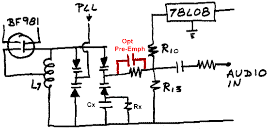
To keep the Varicaps DC biased, we will have to put a large resistor Rx in parallel to Cx. The resistor's value is not important as long as it is high enough to not affect the circuit's Q. Anything above 56K and below 5M ohms should be OK. Lets choose Rx = 100K ohms.
As we have now reduced the total capacitance in the L/C circuit, we have to increase the inductance so that it tunes the same band as before. As we had already squeezed L7 to the extreme to get it to lock at 86 Mhz with 2V of PLL voltage, we cannot increase the inductance by squeezing it further. We will have to take out the existing L7 and put in one of higher value.
If we look at the blue line in the VCO PLL voltage chart above, we see that the PLL needed 7 Volts to lock at 100 MHz. At 7 V, each Varicap making up Cp is 27 pF. Each Varicap making up Ca had 8 Volts across it ie was 25 pF. So the total capacitance was 27/2 + 25/2 = 26 pF. From the first formula on the page, we find that L7 would have had a value of 97 nH. ( This assumes that the Varicaps are the only capacitance in the LC circuit. As the capacitance values we are playing with are small, capacitance of the component leads and even the capacitance of the coil start playing a part. One hobbyist can have different component lead lengths than another, leading to quite different results)
With the modifications we propose, we still want to lock at 86 Mhz with 2 V of PLL voltage. Each Varicap making up Cp will be equal to 45 pF. In parallel to this will be Ca and Cx in series, ie 5.83 pF. Therefore the total capacitance would be 28.33 pF. We therefore now need L7 to be 121 nH.
There are quite a few formulae available to guess at the value of an air coil. They are all very approximate when used for low value small coils like the one we want. The reason is that coils behave one way it the middle and another way near the ends. This is called an "end effect". If the coil has a large length as compared to its dia (l/d > 10), the end effect is less and it is easier to predict the value of the coil's inductance. But in our case, l = d = 6mm approximately (l/d = 1), making it hard to predict the coil's value from formulae. Anyway, lets try one of the popular formulae--
 |
L = inductance in micro-henries l = length of the winding in inches N = the number of turns r = outside radius of the coil in inches |
L7 had a diameter of 6mm, length when compressed around 7mm and with 5 turns. The formula says that its inducance should be 91 nH. We had earlier calculated from Varicap data and frequency of oscillation that L7 when compressed would be 97 nH. I guess the formula was close enough.
So lets use the formula again to design a coil with the new desired inductance of around 121 nH. We will try to design a little spacing in the windings, so that we can compress/expand the coil a bit to reach our desired inductance when theory hits the real world.
Using L = 121 nH, r = 6 mm, l = 8 mm, we find we need 6 turns. If we can squeeze this coil down to 7 mm, it would be about 131 nH while if we expand it to 9 mm, it would be 109 nH. That looks like a decent range centred about the desired 121 nH.
To be continued ( if I ever find the time) .....
WANT TO DISCUSS THE ABOVE ?
Send me e-mails at
web_surf@SPAM-TRAPhotmail.com
Page started on 02 May 1999. We have had page
loads since counter reset on 15 May 2000.