FM
Stereo Transmitter circuit kit MPX Multiplexer Multiplexor FM
exciters FM Transmitters FM Exciter diy Broadcast RF Circuit
electronic
Brief Comments on the NJM2035
20th Oct '99
My look at the NJM2035 Stereo Multiplexer chip by New Japan Radio
( To be read in conjunction with my "Stereo for Dummies"
page )
The Rohm BA1404 tried to do too much on one chip, what with a Stereo Multiplexer, Pilot Generation Circuitry, RF Oscillator and RF Buffer all on board.
On top of that, Rohm's Spec Sheets did not show the basic filters on the input, pilot and MPX that we all know are totally necessary. Low-end Kit manufacturers did not bother to do a bit of basic design homework themselves. They decided to do away with such "niceties" and just rake in the money. Most BA1404 kits are exactly a copy of the Rohm application note with maybe an extra RF stage for little more power.
BA1404 kits started a rash of FAQ's, newsletters, FTP sites. They all concentrated on how to increase power or make it a bit more frequency-stable. Nobody decided to get to the root of the Audio problems - Add the filters. Wavemach came close by using only the Stereo Generator of the BA1404, adding a Compressor/Limiter to prevent clipping/aliasing and ignoring the RF parts of the BA1404.
New Japan Radio's NJM2035 (Specs PDF here) seems to be the nearest contender to the market addressed by the BA1404. But even though the BA1404 is not being produced any more for a long time, Low-end Kit manufacturers did not start making a NJM2035 kit. I think the reason is obvious : The NJM2035 Spec Sheet does not have a suggested PCB while the BA1404 one did ;)
OK, that's enough venom for a day. Let's get technical again.
Can I just unplug my BA1404 and put in a NJM2035 ??????
No, you cannot. The NJM2035 does not have an RF Oscillator and RF Buffer stage. Maybe that is wise as now you have no chance of leakage of the MPX signal to the RF and vice versa. That was one of the internal design flaws of the BA1404.
Is the NJM2035 any good ?????
The NJM2035 is just a Stereo Multiplexor chip using TDM chopping at 38KHz. It does not use oversampling techniques.
The NJM2035's basic electronics seem to give a channel separation of about 35-40 dB, out of which the suggested MPX filter makes you loose about 5-10 dB in the 3-10 KHz range. Pro equipment would aim at 55dB separation.
The NJM2035's distortion figures are about 0.4% -0.6% in the modulation range you will want to use it. Pro equipment would aim for distortion much below 0.1%
The PDF claims Signal to Noise figures of around 67 dB. That's quite fair indeed.
The NJM2035 is made by a respectable company with many other high end Audio processing chips like DNR, Surround Sound, Digital Equalisers.
So all in all, quite a nice chip for the low end. It will definitely outperform the BA1404 and might even sound similar to the cheaper 38 KHz TDM switching kits out there ( But for 20% the cost).
Of course, you should not even remotely consider it for serious broadcasting. It is a toy, but a much better toy than the BA1404 and maybe some of the other simpler kits out there. I would say as a rule of thumb, If all you can afford is 1-7W of RF Power, the rest of your Audio equipment would be such that the NJM2035 would be ideal.
Mods
Don't know if I should call them Mods, as there are no NJM2035 kits out there to begin with. Anyway, here are some engineering notes -
A) The PDF uses hard to obtain values for the MPX filter. Using SPICE, it's a matter of minutes to redesign the MPX filter to original specifications, using more easily available parts. ( A little tad better actually, but what's 0.1 dB amongst friends)
The Goals are that the new filter should remove harmonics centered around 114 KHz ( Third harmonic of 38 KHz) atleast as good as existing circuit. Also, the phase shift should be lower/same as existing circuit.
B) The original PDF shows a pre-emphasis stage with very slight roll-off of the pre-emphasis curve at the high end. We would have loved the pre-emphasis to stop emphasising signals above 15 KHz. Infact, it would be nice if there was a brickwall that stopped signals after 15 KHz altogether. It is also nice to notch out the Audio signals around 19KHz as they interfere with the Pilot Tone and create beats.
Here are some graphics of my work in above directions ---
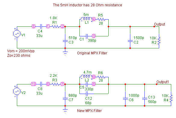
Above, I show the new MPX filter part using more easily available values. My first guess of just plonking in nearest available value failed miserably. The thing has to be tuned quite precisely for effective rejection of the 114 KHz signal.
The 28 Ohm resistor is not a separate physical part, it's just the internal resistance of the 4.7mH inductor I had. I need to show that in SPICE for a perfect simulation, but now, don't you go and add another 28 Ohm in series with your inductor.
SPICE revealed that this is not just a 57 KHz low pass filter as claimed in the PDF, it is actually modified to notch out the 114 KHz part.
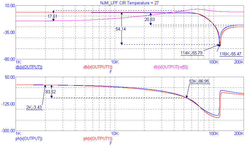
Above chart is an "AC Analysis" of the old and the new MPX filters.
On the top half, I plot OUTPUT ( The old MPX Output), OUTPUT1 (The new MPX output). You can se that the new values used give almost the same amplitude response as the earlier one. The new center frequency is 116 KHz rather than exactly 114 KHz. This does not matter as in reality we are trying to remove signals upto 15 KHz on either side of 114 KHz. So both filters can be considered as equivalent as far as Amplitude response goes.
In the bottom part, I plot the phase of the signals in the original and modified MPX signal. Again we can see that they are quite the same up to 53 KHz. Now we can commit that the two versions of the MPX filters should materially perform the same.
But are they any good ?
We can see a tremendous phase shift of 83.52 degrees between the low end and the 53 KHz point. We are aware that a phase shift in an MPX filter means that certain signals that should have exactly cancelled out will now leave residues in the other channel, degrading crosstalk figures.
So I went ahead and plotted dB(V(OUTPUT) -V(5)) as a pink line on the Amplitude response. This is nothing else but the amplitude difference between the original MPX signal and the output of the filter. Now that means nothing by itself, but is a bit similar to what the decoder in the receiver will do i.e minus the L-R signal from the L+R signal and hope for clean nulling. So if you imagine that the original signal was the L from the L+R part and the output from the filter is the L from the L-R part. Subtracting the two will show you how well does the nulling effect take place.
At the low end, we can see the Pink line is straight up to about 5 KHz. It is below the V(Output) line, this just represents an insertion loss of the filter. Later on, we see that due to phase shifts, the signals don't cancel so well and more of the difference signal is coming through. Infact there is a 17.61 dB difference in cancellation between low end and 53 KHz. Now 53 KHz would be where a 15 KHz Audio signal would reside in the L-R part. 38 KHz + 15 KHz = 53 KHz.
There would also be the lower side band of the L-R signal. A 15 KHz L-R signal would have half its energy at 38 KHz - 15 KHz = 23 KHz. We see from our pink line that the difference signal is +7 dB up at 23 KHz as compared to low frequencies. Our difference in the 15 KHz signal would actually be the average of 17 and 7 dB i.e. 12 dB.
When we see the NJM2035 PDF, we do see that the channel separation at 15 KHz is about 12 dB less than at 1 KHz. This can be attributed almost totally to the MPX filter.
{PLEASE CHECK ABOVE LOGIC FOR YOURSELF. It's from the top of my hat and I need to sit down and rethink if that is really the way crosstalk is predicted from Phase response and cancellation charts}
But here's the Catch 22. If you make a cheap chip or kit that does not oversample, it will have a lot of harmonics at 114 KHz. If you try to notch out the 114 KHz, it needs a drastic MPX filter that will create greater Phase shifts. Phase Shifts reduce your Channel Separation. My Father says it best - Every Problem has a Solution. Every Solution creates a new Problem.
Anybody out there that can suggest a better MPX filter to use with the NJM2035 ???? Looking forward to your SPICE files.
If we think that 12 dB channel separation loss is too high a price to pay for 54 dB suppression around 114 KHz, we could design maybe a 30 dB notch and check out how much separation that makes us loose ?
Now let's look at the Audio Input side of things --
In the FM path from Transmitter to Receiver, more noise is noticed at the high Audio frequencies. Hence the FM standards call for boosting the high frequencies on transmitting. The Receiver is then supposed to reduce the high frequencies in exactly the reciprocal way to the transmitter. In this way, the Receiver reduces the boosted High frequency notes to normal levels, but it also at the same time reduces the received hiss to low levels. Cassette Players also use the same technology. This process of boosting high frequencies upon transmitting/recording and reducing the high frequencies along with the noise upon receiving/playback is called pre-emphasis/de-emphasis.
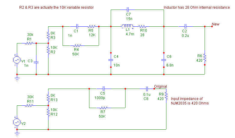
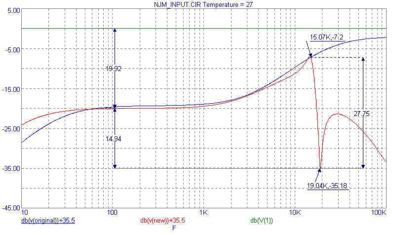
The Green line above is the input signal. The Blue line is the response of existing 50uS pre-emphasis circuit as shown in the NJM2035 PDF. The Red line is the response of my modified filter. I added 35.5dB as that is the gain of the NJM2035.
We can see that the insertion loss of the brickwall that I added is only 0.6dB. This means that the new filter will act the same as the old one in the 20Hz-15KHz region without needing any extra active audio amplification stage.
The aim of this game is to design a filter that as closely as possible follows the Ideal Pre-emphasis graph till 15 KHz and then suddenly drops steeply to -infinity after that. Now that's impossible to achieve in practice. So we settle for a design goal of 1.5 dB overshoot on the graph (the little hill near 15 KHz) and a notch around 19 KHz and a steep roll off after that so that we have no gain around RF. We want incoming Audio signals around 19 KHz to be suppressed as much as possible because they interfere with the Pilot signal and also cause beats.
We purposely went for a 2 dB drop at 20Hz to avoid rumble or low frequency thumps from making the Exciter loosing PLL lock. If you do want a flat response down to 5 Hz, replace last 0.2uF cap with 1uF.
The last thing I need to look at is the final MPX output level. The NJM2035 PDF doesn't say so but the suggested Application circuit only outputs about 60mVpp of final MPX signal. Now that's too low to drive many Exciters that need 500-770mV RMS. So looks like a single stage with an amplification of about 12-15 times is in order. I leave that to the interested reader.
Monte Carlo Simulation
SPICE allows one to specify a tolerance for each component, and then run many trials by randomly choosing components within the tolerance band. You can define a failure criteria and the software will warn you if an unfortunate collection of parts leads to failure of the circuit to perform to basic specs. This way you can check the repeatability of your circuit for mass production, without actually building 50 prototype units.
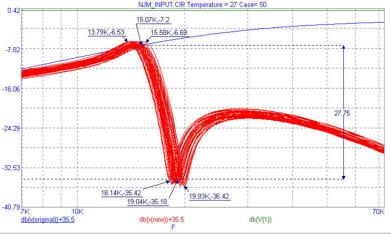
The above chart shows the Monte Carlo simulation for 50 runs on the Audio Brickwall, using parts with 10% tolerance. The actual response you get will be somewhere within the above red band, depending on the actual measured values of components you use. Histograms are also available to monitor key performance variables. From them, I found that above circuit will have a valley between 18.65 - 19.17 KHz for 57% of the random cases.
Oh yes, I would appreciate any assistance in designing a 3 Transi RF Oscillator with good frequency stability and about 100mW RF output. That should give us a much better Yardcaster than we had out there before.
Wanna have your own page here, write
about your own experiences, own review, refute existing review,
add comments to existing review, publish your circuits ?
Contact
me
Page started on 20 Oct 1999. We have had page
loads since counter reset on 15 May 2000.